
On-line monitoring of cable integrity during submarine installation
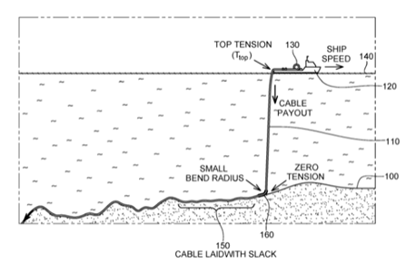
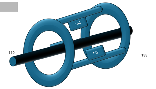
A method and system for determining deformation in a cable 110, wherein a sensing acoustic sensing apparatus is applied along the cable 110 in the proximity of laying ship 130. The method comprises one or more acoustic sensing apparatuses 132 in strict contact or near proximity of the top tension position Ttop continuously measuring the occurrence of noises generated by the movement and deformation of said cable 110.
The system comprises a signal processing unit 135, installed and operated inside the laying ship 130, capable of discretizing and separate the acoustic events generated from within the cable from those generated by external natural or antropic (man generated) events.
This separation is based on expert tools, capable of clustering ad identify efents by direction (internal or external), spectral analysis and phase resolution.
The sensing elements 132 could be either free floating below tha ship m130 or preferably housed in a “rider” annular element 133 (housing multiple sensors 132) that maintains the sensing elements in strict rolling contact with the cable or in the immediate vicinity of the same.
The rider apparatus could be either contactless or provided with rolling elements that “ride” the surface of the cable to maintain the mutual position of 133 with regards to 130.
The rider 133 will be design to allow the necessary clearence between the cable and the sensors, allowing, in particular the unimpeded passage through the rider 133 of particular elements of the cable with a different overall diameter (e.g. factory of field Joints).
The rider 133 will be design to allow the necessary openting of the rider itself, to be utilized both in the preparatory phases (placenment around the cable) or the need to allow tha laying of particularly large components of the cable itself (Rigid repair Joints, bend stiffeners, pull in heads).
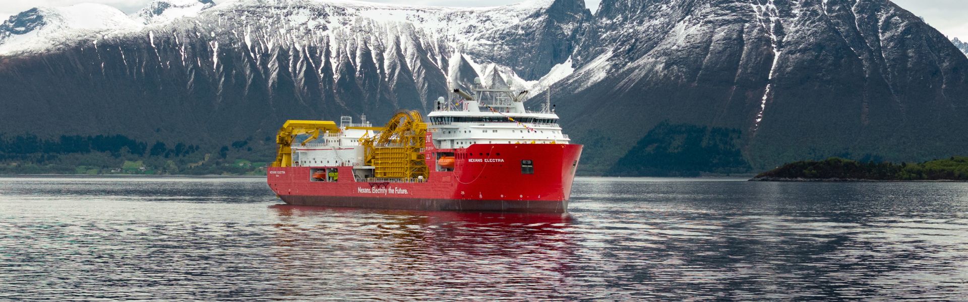
The method and system may be used during deployment of a subsea power cable 110 to a sea bottom 100 from a cable reel 130 positioned on the deck of a cable-laying vessel 120 floating on a sea surface 140.
The length of cable 130 in the vicinity of the ship 130 is the one where the mechanical tension is greater, furthermore the portion over the laying wheel has the most curvature of the entire length and present an abrupt mechanical discontinuity.
It is therefore highly probable that any mechanical failure of cable elements (armour wires or metallic sheaths) would occur in the top part of the cable being installed. Any mechanical element under high stress fails generation characteristic and measurable noise.
The monitoring and identification of the occurrence of such events (acoustic snaps) will allow the prompt repair of the failed element, while the absence of events would be used to guarantee to the Clients that the laying operation has been carried out without negative consequences on the integrity of the cable itself.
An advantage of the method is that, due to the placement of the sensing element near the laying vessel, a very early occurrence could be identified, the length of cable to be recuperated on-board to allow inspection or repairs is therefor minimal, minimizing the delay and disruption of normal operations.
An additional advantage is that the electronic sensors 132 could be easily energized and controlled, via a dedicated umbilical connection from the laying vessel 130.